CanEasy can be configured for a multitude of different applications scenarios. The following section provides exemplary scenarios and tips for the respective configuration.
CanEasy as remaining bus simulation
CanEasy can be used as a remaining bus simulation for CAN and LIN bus systems. In this scenario, messages sent by physical control units are received and the messages and behavior of unavailable control units will be simulated. For this, a DBC or LDF vehicle bus description file must be generated, the control units must be defined as either real or simulated, and the hardware interface for the connected bus must be configured.

CanEasy as residual bus simulation
CanEasy as virtual system
CanEasy can be used as a virtual remaining bus simulation – for instance to analyze the functionality of a generated bus. In this scenario, all control units are defined as simulated. For this, one or more DBC or LDF vehicle bus description files must be generated, all controls units of the bus must be set as simulated, and a virtual bus must be configured using the bus editor. For this scenario, no hardware interface is required to run the simulation.

CanEasy in use as virtual network
Using CanEasy for analysis in real networks
Recording in CanEasy
CanEasy can be set up to record bus communication in just a few steps: First, a new working space must be generated and the hardware interface and bus connection must be defined in the bus editor. After starting the simulation (which is, technically, not simulating anything at the moment), the complete bus traffic is recorded and can be viewed in the trace window. The trace window displays the messages of the connected physical ECUs as “unknown messages” if no description file is loaded for these ECUs. After the recording has finished, it can be analyzed later (e.g. in the lab) using the respective bus description files (DBC or LDF). The recording can of course also be started with previously generated description files.
Analysis in CanEasy
CanEasy can be connected to an existing vehicle network and used as an on-site analysis tool. In this scenario, CanEasy “eavesdrops” on bus communication, recording all transmissions. For this, one or more DBC or LDF must be vehicle bus description files must be generated, all control units must be defined as real, and the connected hardware interface must be configured using the bus editor. All transmitted signals and messages can be analyzed and viewed using CanEasy’s core applications, for instance in trace, plot or signal monitor windows.

CanEasy as analysis tool in a real network
CanEasy as data base editor
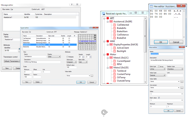
CanEasy can also be used to edit DBC or LDF vehicle bus description files. First, the respective description file must be loaded and will be generated to an internal data base. Next, the existing control units can be edited using CanEasy’s integrated editors (e.g. the message editor or the signal editor). In addition, new control units, messages, or signals can be added to the data base. From the context menu of the bus tree entry, a DBC or LDF can be generated now from the adjusted data base.
▪Import some external communication matrix to see content in CanEasy
▪Modify messages, signals, variables, …
▪Export to external file (e.g. DBC)
Test Sequenzer
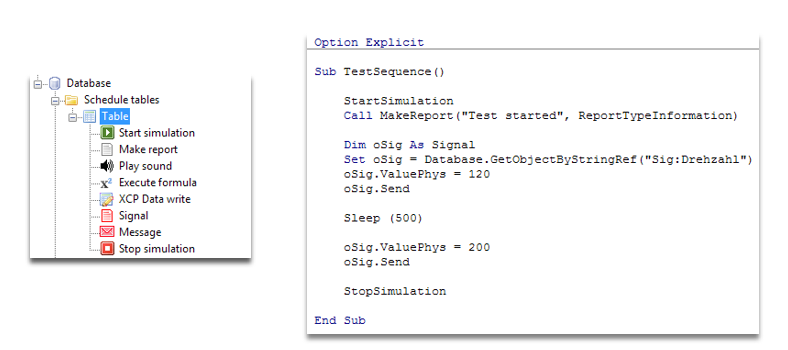
▪Using VBA/VSTA or schedule tables, test sequences can be automated
Hardware abstraction layer
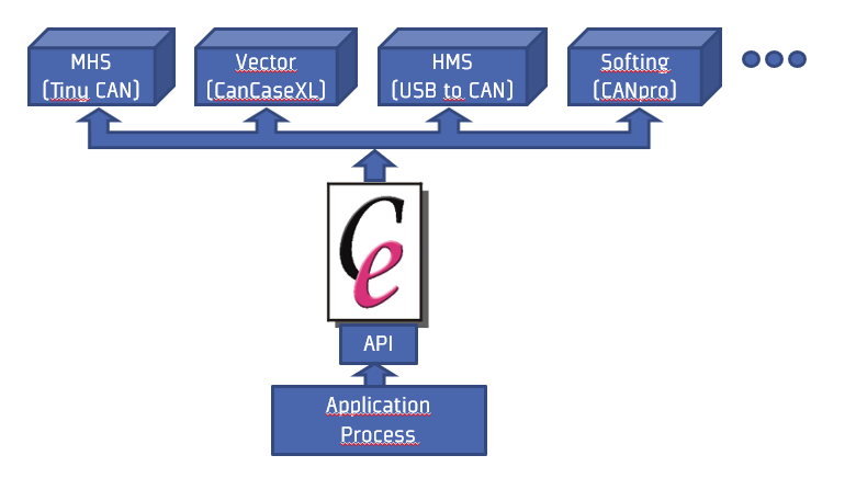
▪Integrate CanEasy into another process to have a uniform access to bus adapters
Demo
▪Virtual system
–Database: Import Car.dbc file
–Hardware: Create new „Schleissheimer Virtual CAN“
–Start simulation and open trace window
> All ECUs are simulated
▪Residual bus simulation
–Database: Set simulation behavior of IC to real
–Hardware: Create new „Schleissheimer Virtual CAN“ with channel id „ExCar-Channel“
–Start Example-Car from Demonstrator-Suite
–Start simulation and open trace window
> Received messages are displayed
> Other ECUs are still simulated
▪Analyse real network
–Set simulation behavior of all ECUs to real (using the context menu of the Car channel
–Start simulation and open trace window
> There is no Tx message any more
▪Datenbase editor
–Set simulation behavior of all ECUs back to simulated
–Set simulation behavior of IC to real
–Start simulation and open trace window
–Create new message under ART
–Create a new signal under the message
–Change TransmissionMode to Cyclic and
set CycleTime property to 100
> CanEasy starts sending this message
–Open message- and signal editor
> Information about editors see „Modify the database“
–Export database as DBC file
> New message is exported to DBC file
▪Test sequenzer
–Create new scheduler table under database
–Create entry „Start simulation“
–Create entry „Make report“ with name „Test started“
–Drag signal CurrentSpeed and drop it to the table
–Change ValueToSet property to 200
–Drag message Motor1 and drop it to the table
–Set property duration to 200
–Create „If condition“ and set name „DisplaySpeed“
–Set property operator to „Smaller“ and Value to 200
–Create report inside of condition with error text „DisplaySpeed error“
–Create entry „Stop simulation“
> Close ExCar and execute table to detect error
▪Hardware abstraction layer
–Create empty workspace
–Create as much channel as you need
–Select hardware->refresh to detect all connected bus adapters
–Assign each database channel to some hardware channel
–Create application to integrate CanEasyApplication COM object and use Bus.SendFreeCanMessage to transmit a message
–Use TransmissionEvent to process received messages