The COM port defines in BSKD7 projects, how the diagnostics is being connected to the bus with its diagnostics channel. This must be defined with the command "cp <port>".
Communication via serial ports (RS232)
With the COM ports 1-8 the access to the serial interfaces COM1-COM8 via Windows API are possible. Also USB-COM interfaces are supported, but in certain circumstances not all bit rates are possible and the time response is not as expected.
|
Communication via CAN interfaces
The following COM ports inside BSKD7 are mapped with the configured buses in CanEasy via the display channel and could be selected via the named command.
BSKD |
CanEasy |
32 |
1 |
33 |
2 |
34 |
3 |
35 |
4 |
... |
... |
63 |
32 |
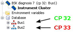
This means: If e.g. two buses were created in the workspace and configured in the bus editor with Bus1 = display channel 1 and Bus2 = display channel 2, the BSKD project has access to the Bus1 via "cp 32" and Bus2 via "cp 33". For the communication the hardware configured for the corresponding bus is used.

Example: The diagnosis is connected via CP 32 to Bus1 actually. Via CP 33 it could be connected to Bus2.
|
Displaying the diagnostics connection (channel mapping)
The tree entry BSK Diagnose 7 displays during a running/active simulation and diagnostics project, to which bus the BSKD7 is connected.
Example:
![]()
In this case the COM port 32 of the BSKD7 is connected to Bus1 (configured display channel 1).
Possible announcements for a diagnostics connection are explained in the subsequent table:
Announcement |
Impact |
cp 32: Bus1 |
COM port 32 of BSKD7 is connected to Bus1. Bus1 is the configured name of the bus within the bus editor. |
cp 128: Bus1 [AIDA 2] |
BSKD7 is connected via the AIDA stacks to Bus1. Thereby AIDA channel 2 is used. |
cp33 |
In the BSKD7 project the COM port 33 is configured. The simulation was stopped, hence it is not possible to display the bus connection. |
cp0: --- |
No valid COM port was configured or bus connection can not be determined yer, hence dashes ("---") are displayed. |