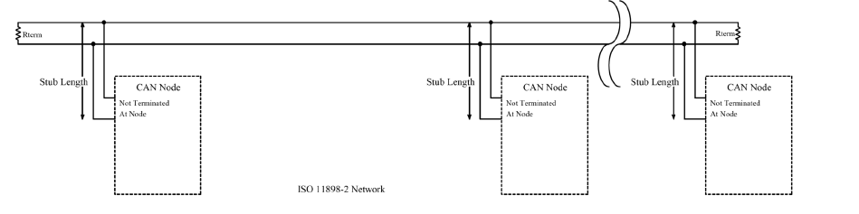
By default, CAN bus systems are built using two parallel data cables, although a single cable would be theoretically sufficient. Using two data cables makes the system safer and less prone to failure, because the network will still function even if one data cable is defective or broken. The ECUs are connected to both data cables consecutively via short stubs. As a result, the bus system functions even if an ECU fails completely. This would be impossible in a circular structure
The linear topology of CAN buses reduces the number and length of cables in vehicles, saving both weight and cost.
In automotive technology, a distinction between high-speed CAN buses with maximum transfer rates (baud rates) of up to 1 Mbit/s and low-speed CAN buses transferring up to 125 Kbit/s is made.
High-speed CAN buses are used for control units which must exchange information quickly, e.g. engine electronics, airbag or ABS units. Comfort systems like climate controls, display systems or door ECUs communicate on low-speed CAN buses. The high transfer speeds of CAN buses make them suitable for real-time communication.
In shorts:
•Linear topology (reduces the number and length of cables in vehicles)
•Multi-Master communication
•Carrier Sense Multiple Access/Collision Resolution (CSMA/CR)
•CAN bus systems are built using two parallel data cables (differential signal)
•Logical „1“ is recessive and logical „0“ is dominate (Wired-AND)
•For higher baud rates termination resistors are necessary at the ends (e.g. 120 Ω)to avoid reflections